KIT 4506
V-TAIL BONANZA
COPYRIGHT 2013 BY PAUL K. GUILLOW, INC.
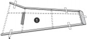
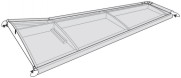
You will build the wing frames directly over layouts. To ensure that they are built straight, tape this sheet on a flat surface and tape parts down as shown. If you have a workboard you can exchange the tape for common pins to hold parts down.
First carefully remove all laser cut parts from the balsa sheets. Use white glue (or with adult supervision a fast drying glue like super glue) for assembling your model. Glue can be purchased at your local hobby or hardware store.
NOTE: This model will fly well with one loop of rubber thread, but if you want to give it more speed / climb try two loops of rubber motor. (You have enough rubber to make & fly both options.)
FLIGHT INSTRUCTIONS
Check the balance of your model by putting your fingertips under the wing at the balance point (approx ½” back from the leading edge) and picking up, the airplane should hang level or slightly nose heavy. Use the stick on weights included in the kit to achieve this. Test glide model before making powered flights, hold model beneath wing and launch gently forward into any breeze. If plane noses up or dives into ground add or subtract some weight. After proper corrections, wind motor clockwise about 100 to 125 turns and launch straight. Model can be flown in a gym or outside on a calm day.
KIT 4506
WING FRAME LAYOUT SHEET
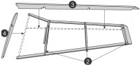
Terms and notes to know on Wing Layouts
END VIEW (Before dihedral
is added)
NOTE: SLANT - FOR WING DIHEDRAL (The angle needed to give the plane stability)
Visit our website for helpful 3D model files and assembly videos.
www.guillow.com/3Dassembly.aspx
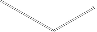
Lightly score the
line in the center of
the rudder. ‘Snap’ the
rudder along the score line
and glue to line up with this
120° V outline.
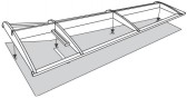
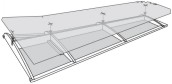
COVERING WING FRAMES
Cut out decals just inside the outer edge lines.
2. Line the
+s on top decal up with where the wing ribs and center keel meet.
3. Wrap flaps over leading and trailing edges and press down.
4. Wrap wing tip flaps over the edge of the wing tip.
5. Repeat with other wing.
1. Place the bottom decal, sticky side up, on your work surface and align the
+s with the wing ribs. Press down.
1. Tape W1 - W4 over right wing on plan and glue together.
2. Glue W5 - W7 ribs into slots on the leading and trailing edges.
3. Slide W9 center spar down into slots and glue into place.
4. Glue W8 rib in place, making sure it butts up to W9
5. Let dry and repeat for left wing.
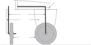
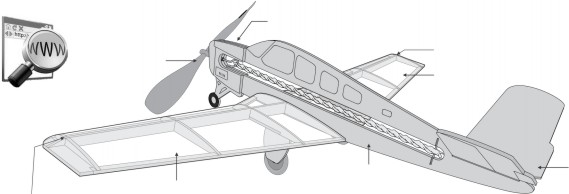
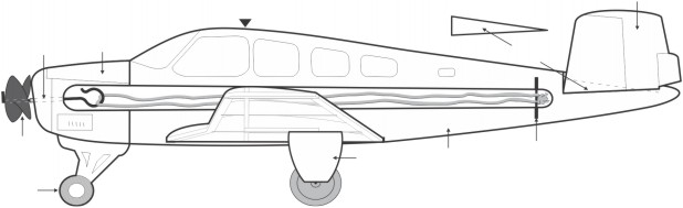
1. Glue one nose brace onto the front of the fuselage.
2. Glue the tube of the propeller unit into the nose of the fuselage (Be sure not to get glue on the prop wire).
3. Glue the other nose brace on the other side of the fuselage, securing the propeller unit into place.
4. Glue front wheel onto the fuselage.
5. Cut and glue wire for rear motor mount into slot.
6. Score, bend and glue v-tail at the angle shown in the v-tail template. When dry, glue onto fuselage. Be careful it is glued on straight. Glue rear fuselage piece on top.
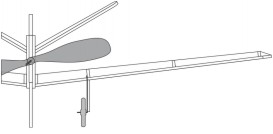
7. Glue assembled wings into the slots on fuselage. Hold until dry. Check wing angle from front of the model.
8. Loop rubber band motor around rear motor mount and propeller hook. Tie knot. (See note)
9. Assemble and install the landing gear, if desired (see note). Be careful to build one left & one right assembly.
NOTE: If you would like
to build a lighter & better
flying model, build it without
the landing gear.
Glue landing gear
to wing up through
W4 slot.
Bend landing gear
wire and assemble
landing gear. Cut off
the extra wire with
wire cutters.